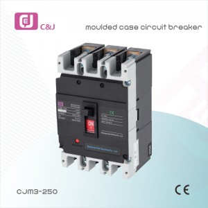
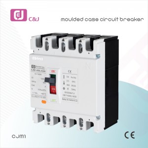
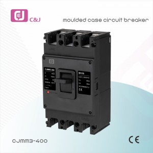
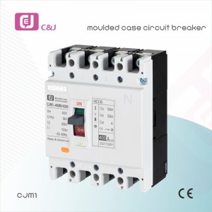
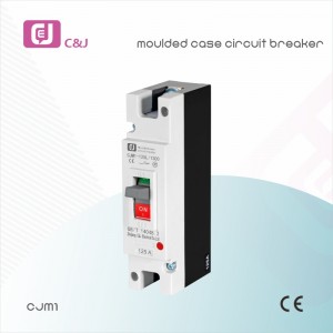
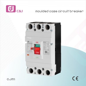
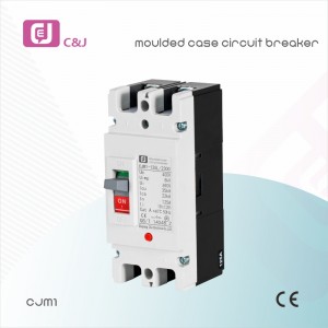
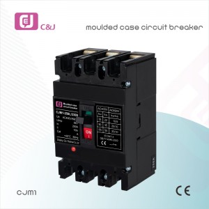
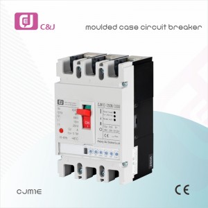
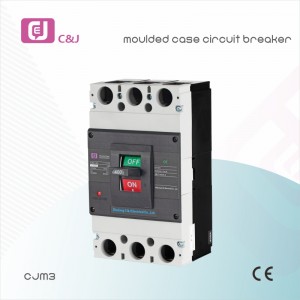
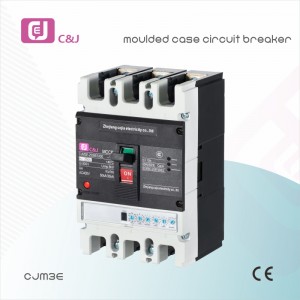
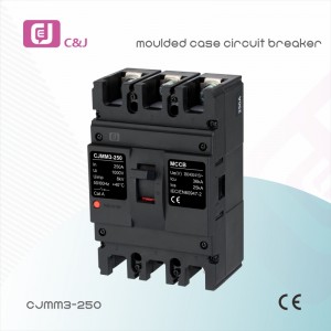
China Manufacturer CJMM1 125A 4P PV MCCB DC Moulded case circuit breaker
Product Model
CJMM:Enterprise code
M:Moulded case circuit breaker
1:Design No
□:Rated current of frame
□:Breaking capacity characteristic code/S denotes standard type (S can be omitted)H denotes higher type
Note: There are four types of neutral pole (N pole) for four phases product.The neutral pole of type A is not equipped with over-current tripping element, its always switched on, and it is not switched on or off together with other three poles.
The neutral pole of type B is not equipped with over-current tripping element, and it’s switched on or off together with other three poles(the neutral pole is switched on before being switched off)The neutral pole of type C is equipped with over-current tripping element, and it’s switched on or off together with other three poles(the neutral pole is switched on before being switched off) The neutral pole of type D is equipped with over-current tripping element, it’s always switched on and is not switched on or off together with other three poles.
Table 1
| Accessory name | Electronic release | Compound release | ||||||
| Auxiliary contact,under voltage release,alam contact | 287 | 378 | ||||||
| Two auxiliary contact sets,alarm contact | 268 | 368 | ||||||
| Shunt release, alarm contact, auxiliary contact | 238 | 348 | ||||||
| Under voltage release,alarm contact | 248 | 338 | ||||||
| Auxiliary contact alarm contact | 228 | 328 | ||||||
| Shunt release alarm contact | 218 | 318 | ||||||
| Auxiliary contact under-voltage release | 270 | 370 | ||||||
| Two auxiliary contact sets | 260 | 360 | ||||||
| Shunt release under-voltage release | 250 | 350 | ||||||
| Shunt release auxiliary contact | 240 | 340 | ||||||
| Under-voltage release | 230 | 330 | ||||||
| Auxiliary contact | 220 | 320 | ||||||
| Shunt release | 210 | 310 | ||||||
| Alarm contact | 208 | 308 | ||||||
| No accessory | 200 | 300 | ||||||
Classification
- By breaking capacity: a standard type(type S) b higher breaking capacity type(type H)
- By connection mode: a front board connection, b back board connection, c plugin type
- By operation mode: a direct handle operation, b rotation handle operation,c electrical operation
- By number of poles: 1P, 2P, 3P, 4P
- By accessory: alarm contact, auxiliary contact, shunt release, under voltage release
Normal Service Condition
- The altitude of the installation site shall not exceed 2000m
- Ambient air temperature
- The ambient air temperature shall not exceed +40℃
- The average value shall not exceed +35℃ with in 24 hours
- The ambient air temperature shall not be less than -5℃
- Atmosphere condition:
- 1There lative humidity of atmosp here shall not exceed 50% at highest temperature of +40℃,and it can be higher atalower temperature,when theaver agelowest temperature in the wettest month doesn’t exceed 25℃ can be 90%,conden sationon product surfacedue to temperature change must be takenin to account.
- The pollution level is class 3
Main Technical Parameter
| 1 Rated value of circuit breakers | ||||||||
| Model | Imax (A) | Specifications (A) | Rated Operation Voltage(V) | Rated Insulation Voltage(V) | Icu (kA) | Ics (kA) | Number of Poles (P) | Arcing Distance (mm) |
| CJMM1-63S | 63 | 6,10,16,20 25,32,40, 50,63 |
400 | 500 | 10* | 5* | 3 | ≤50 |
| CJMM1-63H | 63 | 400 | 500 | 15* | 10* | 3,4 | ||
| CJMM1-100S | 100 | 16,20,25,32 40,50,63, 80,100 |
690 | 800 | 35/10 | 22/5 | 3 | ≤50 |
| CJMM1-100H | 100 | 400 | 800 | 50 | 35 | 2,3,4 | ||
| CJMM1-225S | 225 | 100,125, 160,180, 200,225 |
690 | 800 | 35/10 | 25/5 | 3 | ≤50 |
| CJMM1-225H | 225 | 400 | 800 | 50 | 35 | 2,3,4 | ||
| CJMM1-400S | 400 | 225,250, 315,350, 400 |
690 | 800 | 50/15 | 35/8 | 3,4 | ≤100 |
| CJMM1-400H | 400 | 400 | 800 | 65 | 35 | 3 | ||
| CJMM1-630S | 630 | 400,500, 630 |
690 | 800 | 50/15 | 35/8 | 3,4 | ≤100 |
| CJMM1-630H | 630 | 400 | 800 | 65 | 45 | 3 | ||
| Note: When the test parameters for the 400V, 6A without heating release | ||||||||
| 2 Inverse time breaking operation characteristic when each pole of overcurrent release for power distribution is powered on at the same time | ||||||||
| Item of test Current (I/In) | Test time area | Initial state | ||||||
| Non-tripping current 1.05In | 2h(n>63A),1h(n<63A) | Cold state | ||||||
| Tripping current 1.3In | 2h(n>63A),1h(n<63A) | Proceed immediately after No.1 test |
||||||
| 3 Inverse time breaking operation characteristic when each pole of over- current release for motor protection is powered on at the same time. |
||||||||
| Setting Current Conventional time Initial State | Note | |||||||
| 1.0In | >2h | Cold State | ||||||
| 1.2In | ≤2h | Proceeded immediately after the No.1 test | ||||||
| 1.5In | ≤4min | Cold State | 10≤In≤225 | |||||
| ≤8min | Cold State | 225≤In≤630 | ||||||
| 7.2In | 4s≤T≤10s | Cold State | 10≤In≤225 | |||||
| 6s≤T≤20s | Cold State | 225≤In≤630 | ||||||
| 4 The instantaneous operation characteristic of circuit breaker for power distribution shall be set as 10in+20%, and the one of circuit breaker for motor protection shall be set as12ln±20% |
Outline Installation Size
CJMM1-63, 100, 225, Outline and Installation Sizes (Front board connection)
| Sizes(mm) | Model Code | |||||||
| CJMM1-63S | CJMM1-63H | CJMM1-63S | CJMM1-100S | CJMM1-100H | CJMM1-225S | CJMM1-225 | ||
| Outline Sizes | C | 85.0 | 85.0 | 88.0 | 88.0 | 102.0 | 102.0 | |
| E | 50.0 | 50.0 | 51.0 | 51.0 | 60.0 | 52.0 | ||
| F | 23.0 | 23.0 | 23.0 | 22.5 | 25.0 | 23.5 | ||
| G | 14.0 | 14.0 | 17.5 | 17.5 | 17.0 | 17.0 | ||
| G1 | 6.5 | 6.5 | 6.5 | 6.5 | 11.5 | 11.5 | ||
| H | 73.0 | 81.0 | 68.0 | 86.0 | 88.0 | 103.0 | ||
| H1 | 90.0 | 98.5 | 86.0 | 104.0 | 110.0 | 127.0 | ||
| H2 | 18.5 | 27.0 | 24.0 | 24.0 | 24.0 | 24.0 | ||
| H3 | 4.0 | 4.5 | 4.0 | 4.0 | 4.0 | 4.0 | ||
| H4 | 7.0 | 7.0 | 7.0 | 7.0 | 5.0 | 5.0 | ||
| L | 135.0 | 135.0 | 150.0 | 150.0 | 165.0 | 165.0 | ||
| L1 | 170.0 | 173.0 | 225.0 | 225.0 | 360.0 | 360.0 | ||
| L2 | 117.0 | 117.0 | 136.0 | 136.0 | 144.0 | 144.0 | ||
| W | 78.0 | 78.0 | 91.0 | 91.0 | 106.0 | 106.0 | ||
| W1 | 25.0 | 25.0 | 30.0 | 30.0 | 35.0 | 35.0 | ||
| W2 | - | 100.0 | - | 120.0 | - | 142.0 | ||
| W3 | - | - | 65.0 | 65.0 | 75.0 | 75.0 | ||
| Install Sizes | A | 25.0 | 25.0 | 30.0 | 30.0 | 35.0 | 35.0 | |
| B | 117.0 | 117.0 | 128.0 | 128.0 | 125.0 | 125.0 | ||
| od | 3.5 | 3.5 | 4.5 | 4.5 | 5.5 | 5.5 | ||
CJMM1-400,630,800,Outline and Installation Sizes (Front board connection)
| Sizes(mm) | Model Code | |||||||
| CJMM1-400S | CJMM1-630S | |||||||
| Outline Sizes | C | 127 | 134 | |||||
| C1 | 173 | 184 | ||||||
| E | 89 | 89 | ||||||
| F | 65 | 65 | ||||||
| G | 26 | 29 | ||||||
| G1 | 13.5 | 14 | ||||||
| H | 107 | 111 | ||||||
| H1 | 150 | 162 | ||||||
| H2 | 39 | 44 | ||||||
| H3 | 6 | 6.5 | ||||||
| H4 | 5 | 7.5 | ||||||
| H5 | 4.5 | 4.5 | ||||||
| L | 257 | 271 | ||||||
| L1 | 465 | 475 | ||||||
| L2 | 225 | 234 | ||||||
| W | 150 | 183 | ||||||
| W1 | 48 | 58 | ||||||
| W2 | 198 | 240 | ||||||
| A | 44 | 58 | ||||||
| Install Sizes | A1 | 48 | 58 | |||||
| B | 194 | 200 | ||||||
| Od | 8 | 7 | ||||||
Back Board Connection Cut-out Diagram Plug In
| Sizes(mm) | Model Code | ||||||
| CJMM1-63S CJMM1-63H |
CJMM1-100S CJMM1-100H |
CJMM1-225S CJMM1-225H |
CJMM1-400S | CJMM1-400H | CJMM1-630S CJMM1-630H |
||
| Sizes Of Back Board Connection Plug in Type | A | 25 | 30 | 35 | 44 | 44 | 58 |
| od | 3.5 | 4.5*6 deep hole |
3.3 | 7 | 7 | 7 | |
| od1 | - | - | - | 12.5 | 12.5 | 16.5 | |
| od2 | 6 | 8 | 8 | 8.5 | 9 | 8.5 | |
| oD | 8 | 24 | 26 | 31 | 33 | 37 | |
| oD1 | 8 | 16 | 20 | 33 | 37 | 37 | |
| H6 | 44 | 68 | 66 | 60 | 65 | 65 | |
| H7 | 66 | 108 | 110 | 120 | 120 | 125 | |
| H8 | 28 | 51 | 51 | 61 | 60 | 60 | |
| H9 | 38 | 65.5 | 72 | - | 83.5 | 93 | |
| H10 | 44 | 78 | 91 | 99 | 106.5 | 112 | |
| H11 | 8.5 | 17.5 | 17.5 | 22 | 21 | 21 | |
| L2 | 117 | 136 | 144 | 225 | 225 | 234 | |
| L3 | 117 | 108 | 124 | 194 | 194 | 200 | |
| L4 | 97 | 95 | 9 | 165 | 163 | 165 | |
| L5 | 138 | 180 | 190 | 285 | 285 | 302 | |
| L6 | 80 | 95 | 110 | 145 | 155 | 185 | |
| M | M6 | M8 | M10 | - | - | - | |
| K | 50.2 | 60 | 70 | 60 | 60 | 100 | |
| J | 60.7 | 62 | 54 | 129 | 129 | 123 | |
| M1 | M5 | M8 | M8 | M10 | M10 | M12 | |
| W1 | 25 | 35 | 35 | 44 | 44 | 58 | |
What is DC MCCB?
Understanding DC MCCB: A Comprehensive Guide
In the field of electrical engineering and power distribution, the term “MCCB” appears frequently. MCCB stands for Molded Case Circuit Breaker and is a critical component in protecting circuits from overcurrent, short circuits and other electrical faults. While AC MCCBs are widely discussed, DC MCCBs are equally important, especially in applications involving direct current (DC) systems. This blog aims to demystify DC molded case circuit breakers and discuss their functions, applications and advantages.
What is a DC molded case circuit breaker?
DC Molded Case Circuit Breaker (DC MCCB) or DC Molded Case Circuit Breaker is a circuit breaker specially designed to protect DC circuits. Unlike their AC counterparts, DC MCCBs are designed to address the unique challenges presented by DC, such as the lack of a zero-crossing point and the potential for sustained arcing. These circuit breakers are essential in various industries, including renewable energy, transportation and telecommunications, which commonly use DC power systems.
How does a DC molded case circuit breaker work?
The main function of DC molded case circuit breaker is to interrupt the current in case of overload or short circuit. Here’s a step-by-step breakdown of how it works:
1. Detection: The DC molded case circuit breaker continuously monitors the current flowing through the circuit. If the current exceeds the rated capacity of the circuit breaker, the protection mechanism is triggered.
2. Interruption: When overcurrent is detected, the circuit breaker opens its contacts to interrupt the current flow. This action prevents damage to the circuit and connected equipment.
3. Arc Extinguishing: One of the major challenges in DC systems is the formation of arcs. When the contacts open, an arc forms due to the continuity of the DC current. DC molded case circuit breakers are equipped with arc extinguishing mechanisms, such as arc extinguishing chambers or magnetic blow arc extinguishing devices, to safely dissipate arcs.
4. Reset: After the fault is cleared, the circuit breaker can be reset manually or automatically to resume normal operation.
Main features of DC molded case circuit breaker
DC molded case circuit breakers have several features that make them suitable for DC applications:
- High Breaking Capacity: They are designed to handle high fault currents, ensuring reliable protection even in harsh environments.
- Thermal and Magnetic Trip Units: These units provide dual protection by responding to prolonged overcurrent (thermal) and momentary short circuit (magnetic).
- Adjustable Trip Settings: Many DC MCCBs offer adjustable trip settings, allowing customization to specific application requirements.
- Compact Design: The molded housing design ensures a compact and rugged form factor, making it easy to integrate into a variety of systems.
Application of DC Molded Case Circuit Breaker
DC molded case circuit breakers are widely used in various industries and scenarios:
- Renewable Energy: Solar power systems, wind turbines and energy storage systems often use DC molded case circuit breakers to protect their circuits.
- Electric Vehicles (EV): DC molded case circuit breakers are used in electric vehicle charging stations and on-board systems to ensure safe operation.
- Telecommunications: Telecommunications infrastructure that relies heavily on DC power uses these circuit breakers to protect critical equipment.
- Industrial Automation: DC Molded Case Circuit Breakers are used in various industrial processes using DC motors and drives.
Benefits of using DC molded case circuit breakers
- Enhanced Safety: DC molded case circuit breakers enhance the safety of electrical systems and personnel by providing reliable overcurrent and short circuit protection.
- REDUCED DOWNTIME: Rapid interruption of failures minimizes damage and reduces downtime, ensuring continuous operation of critical systems.
- Cost-Effective: Prevent damage to expensive equipment and reduce maintenance costs, making DC Molded Case Circuit Breakers a cost-effective solution.
In summary
DC molded case circuit breaker is an indispensable component in modern electrical systems, providing strong protection and ensuring the safe operation of DC circuits. Understanding its functions, characteristics, and applications can help engineers and technicians make informed decisions when designing and maintaining DC power systems. As the demand for renewable energy and electric vehicles continues to grow, the importance of DC molded case circuit breakers will only increase, making them an essential part of our power infrastructure.


