China OEM Mccb Single Phase Factory - CJMM1 Series Moulded Case Circuit Breakers(MCCB) – C&J
China OEM Mccb Single Phase Factory - CJMM1 Series Moulded Case Circuit Breakers(MCCB) – C&J Detail:
Product Model
CJ:Enterprise code
M:Moulded case circuit breaker
1:Design No
□:Rated current of frame
□:Breaking capacity characteristic code/S denotes standard type (S can be omitted)H denotes higher type
Note: There are four types of neutral pole (N pole) for four phases product.The neutral pole of type A is not equipped with over-current tripping element, its always switched on, and it is not switched on or off together with other three poles.
The neutral pole of type B is not equipped with over-current tripping element, and it’s switched on or off together with other three poles(the neutral pole is switched on before being switched off)The neutral pole of type C is equipped with over-current tripping element, and it’s switched on or off together with other three poles(the neutral pole is switched on before being switched off) The neutral pole of type D is equipped with over-current tripping element, it’s always switched on and is not switched on or off together with other three poles.
Table 1
| Accessory name | Electronic release | Compound release | ||||||
| Auxiliary contact,under voltage release,alam contact | 287 | 378 | ||||||
| Two auxiliary contact sets,alarm contact | 268 | 368 | ||||||
| Shunt release, alarm contact, auxiliary contact | 238 | 348 | ||||||
| Under voltage release,alarm contact | 248 | 338 | ||||||
| Auxiliary contact alarm contact | 228 | 328 | ||||||
| Shunt release alarm contact | 218 | 318 | ||||||
| Auxiliary contact under-voltage release | 270 | 370 | ||||||
| Two auxiliary contact sets | 260 | 360 | ||||||
| Shunt release under-voltage release | 250 | 350 | ||||||
| Shunt release auxiliary contact | 240 | 340 | ||||||
| Under-voltage release | 230 | 330 | ||||||
| Auxiliary contact | 220 | 320 | ||||||
| Shunt release | 210 | 310 | ||||||
| Alarm contact | 208 | 308 | ||||||
| No accessory | 200 | 300 | ||||||
Classification
- By breaking capacity: a standard type(type S) b higher breaking capacity type(type H)
- By connection mode: a front board connection, b back board connection, c plugin type
- By operation mode: a direct handle operation, b rotation handle operation,c electrical operation
- By number of poles: 1P, 2P, 3P, 4P
- By accessory: alarm contact, auxiliary contact, shunt release, under voltage release
Normal Service Condition
- The altitude of the installation site shall not exceed 2000m
- Ambient air temperature
- The ambient air temperature shall not exceed +40℃
- The average value shall not exceed +35℃ with in 24 hours
- The ambient air temperature shall not be less than -5℃
- Atmosphere condition:
- 1There lative humidity of atmosp here shall not exceed 50% at highest temperature of +40℃,and it can be higher atalower temperature,when theaver agelowest temperature in the wettest month doesn’t exceed 25℃ can be 90%,conden sationon product surfacedue to temperature change must be takenin to account.
- The pollution level is class 3
Main Technical Parameter
| 1 Rated value of circuit breakers | ||||||||
| Model | Imax (A) | Specifications (A) | Rated Operation Voltage(V) | Rated Insulation Voltage(V) | Icu (kA) | Ics (kA) | Number of Poles (P) | Arcing Distance (mm) |
| CJMM1-63S | 63 | 6,10,16,20 25,32,40, 50,63 |
400 | 500 | 10* | 5* | 3 | ≤50 |
| CJMM1-63H | 63 | 400 | 500 | 15* | 10* | 3,4 | ||
| CJMM1-100S | 100 | 16,20,25,32 40,50,63, 80,100 |
690 | 800 | 35/10 | 22/5 | 3 | ≤50 |
| CJMM1-100H | 100 | 400 | 800 | 50 | 35 | 2,3,4 | ||
| CJMM1-225S | 225 | 100,125, 160,180, 200,225 |
690 | 800 | 35/10 | 25/5 | 3 | ≤50 |
| CJMM1-225H | 225 | 400 | 800 | 50 | 35 | 2,3,4 | ||
| CJMM1-400S | 400 | 225,250, 315,350, 400 |
690 | 800 | 50/15 | 35/8 | 3,4 | ≤100 |
| CJMM1-400H | 400 | 400 | 800 | 65 | 35 | 3 | ||
| CJMM1-630S | 630 | 400,500, 630 |
690 | 800 | 50/15 | 35/8 | 3,4 | ≤100 |
| CJMM1-630H | 630 | 400 | 800 | 65 | 45 | 3 | ||
| Note: When the test parameters for the 400V, 6A without heating release | ||||||||
| 2 Inverse time breaking operation characteristic when each pole of overcurrent release for power distribution is powered on at the same time | ||||||||
| Item of test Current (I/In) | Test time area | Initial state | ||||||
| Non-tripping current 1.05In | 2h(n>63A),1h(n<63A) | Cold state | ||||||
| Tripping current 1.3In | 2h(n>63A),1h(n<63A) | Proceed immediately after No.1 test |
||||||
| 3 Inverse time breaking operation characteristic when each pole of over- current release for motor protection is powered on at the same time. |
||||||||
| Setting Current Conventional time Initial State | Note | |||||||
| 1.0In | >2h | Cold State | ||||||
| 1.2In | ≤2h | Proceeded immediately after the No.1 test | ||||||
| 1.5In | ≤4min | Cold State | 10≤In≤225 | |||||
| ≤8min | Cold State | 225≤In≤630 | ||||||
| 7.2In | 4s≤T≤10s | Cold State | 10≤In≤225 | |||||
| 6s≤T≤20s | Cold State | 225≤In≤630 | ||||||
| 4 The instantaneous operation characteristic of circuit breaker for power distribution shall be set as 10in+20%, and the one of circuit breaker for motor protection shall be set as12ln±20% |
Outline Installation Size
CJMM1-63, 100, 225, Outline and Installation Sizes (Front board connection)
| Sizes(mm) | Model Code | |||||||
| CJMM1-63S | CJMM1-63H | CJMM1-63S | CJMM1-100S | CJMM1-100H | CJMM1-225S | CJMM1-225 | ||
| Outline Sizes | C | 85.0 | 85.0 | 88.0 | 88.0 | 102.0 | 102.0 | |
| E | 50.0 | 50.0 | 51.0 | 51.0 | 60.0 | 52.0 | ||
| F | 23.0 | 23.0 | 23.0 | 22.5 | 25.0 | 23.5 | ||
| G | 14.0 | 14.0 | 17.5 | 17.5 | 17.0 | 17.0 | ||
| G1 | 6.5 | 6.5 | 6.5 | 6.5 | 11.5 | 11.5 | ||
| H | 73.0 | 81.0 | 68.0 | 86.0 | 88.0 | 103.0 | ||
| H1 | 90.0 | 98.5 | 86.0 | 104.0 | 110.0 | 127.0 | ||
| H2 | 18.5 | 27.0 | 24.0 | 24.0 | 24.0 | 24.0 | ||
| H3 | 4.0 | 4.5 | 4.0 | 4.0 | 4.0 | 4.0 | ||
| H4 | 7.0 | 7.0 | 7.0 | 7.0 | 5.0 | 5.0 | ||
| L | 135.0 | 135.0 | 150.0 | 150.0 | 165.0 | 165.0 | ||
| L1 | 170.0 | 173.0 | 225.0 | 225.0 | 360.0 | 360.0 | ||
| L2 | 117.0 | 117.0 | 136.0 | 136.0 | 144.0 | 144.0 | ||
| W | 78.0 | 78.0 | 91.0 | 91.0 | 106.0 | 106.0 | ||
| W1 | 25.0 | 25.0 | 30.0 | 30.0 | 35.0 | 35.0 | ||
| W2 | - | 100.0 | - | 120.0 | - | 142.0 | ||
| W3 | - | - | 65.0 | 65.0 | 75.0 | 75.0 | ||
| Install Sizes | A | 25.0 | 25.0 | 30.0 | 30.0 | 35.0 | 35.0 | |
| B | 117.0 | 117.0 | 128.0 | 128.0 | 125.0 | 125.0 | ||
| od | 3.5 | 3.5 | 4.5 | 4.5 | 5.5 | 5.5 | ||
CJMM1-400,630,800,Outline and Installation Sizes (Front board connection)
| Sizes(mm) | Model Code | |||||||
| CJMM1-400S | CJMM1-630S | |||||||
| Outline Sizes | C | 127 | 134 | |||||
| C1 | 173 | 184 | ||||||
| E | 89 | 89 | ||||||
| F | 65 | 65 | ||||||
| G | 26 | 29 | ||||||
| G1 | 13.5 | 14 | ||||||
| H | 107 | 111 | ||||||
| H1 | 150 | 162 | ||||||
| H2 | 39 | 44 | ||||||
| H3 | 6 | 6.5 | ||||||
| H4 | 5 | 7.5 | ||||||
| H5 | 4.5 | 4.5 | ||||||
| L | 257 | 271 | ||||||
| L1 | 465 | 475 | ||||||
| L2 | 225 | 234 | ||||||
| W | 150 | 183 | ||||||
| W1 | 48 | 58 | ||||||
| W2 | 198 | 240 | ||||||
| A | 44 | 58 | ||||||
| Install Sizes | A1 | 48 | 58 | |||||
| B | 194 | 200 | ||||||
| Od | 8 | 7 | ||||||
Back Board Connection Cut-out Diagram Plug In
| Sizes(mm) | Model Code | ||||||
| CJMM1-63S CJMM1-63H |
CJMM1-100S CJMM1-100H |
CJMM1-225S CJMM1-225H |
CJMM1-400S | CJMM1-400H | CJMM1-630S CJMM1-630H |
||
| Sizes Of Back Board Connection Plug in Type | A | 25 | 30 | 35 | 44 | 44 | 58 |
| od | 3.5 | 4.5*6 deep hole |
3.3 | 7 | 7 | 7 | |
| od1 | - | - | - | 12.5 | 12.5 | 16.5 | |
| od2 | 6 | 8 | 8 | 8.5 | 9 | 8.5 | |
| oD | 8 | 24 | 26 | 31 | 33 | 37 | |
| oD1 | 8 | 16 | 20 | 33 | 37 | 37 | |
| H6 | 44 | 68 | 66 | 60 | 65 | 65 | |
| H7 | 66 | 108 | 110 | 120 | 120 | 125 | |
| H8 | 28 | 51 | 51 | 61 | 60 | 60 | |
| H9 | 38 | 65.5 | 72 | - | 83.5 | 93 | |
| H10 | 44 | 78 | 91 | 99 | 106.5 | 112 | |
| H11 | 8.5 | 17.5 | 17.5 | 22 | 21 | 21 | |
| L2 | 117 | 136 | 144 | 225 | 225 | 234 | |
| L3 | 117 | 108 | 124 | 194 | 194 | 200 | |
| L4 | 97 | 95 | 9 | 165 | 163 | 165 | |
| L5 | 138 | 180 | 190 | 285 | 285 | 302 | |
| L6 | 80 | 95 | 110 | 145 | 155 | 185 | |
| M | M6 | M8 | M10 | - | - | - | |
| K | 50.2 | 60 | 70 | 60 | 60 | 100 | |
| J | 60.7 | 62 | 54 | 129 | 129 | 123 | |
| M1 | M5 | M8 | M8 | M10 | M10 | M12 | |
| W1 | 25 | 35 | 35 | 44 | 44 | 58 | |
What is MCCB?
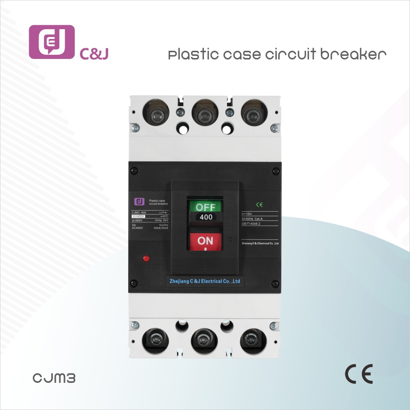
MCCB is shorthand for Moulded Case Circuit Breaker. When the total current surpasses the limitation of a micro fuse box, the user employs it as just another sort of overcurrent protection device. The MCCB protects from overvoltages as well as fault current failures, as well as shifting the circuits.
Users may utilize it even in household applications for more outstanding current ratings and fault occurs levels. Users use MCCBs in commercial processes because of their average comprehensive ratings and high breakdown capacity. MCCBs can also safeguard capacitor banks, generators, and the distribution of main electric feeders. When an application requires discriminatory practices, customizable overloading settings, or ground-fault security, it provides suitable protection.
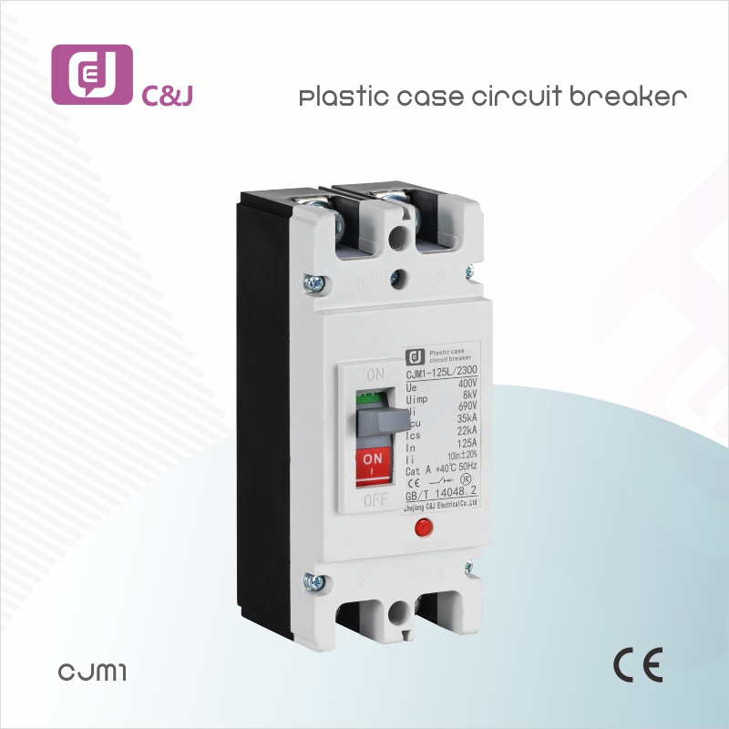
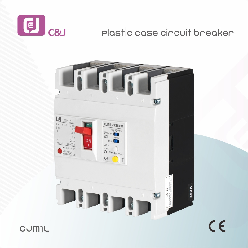
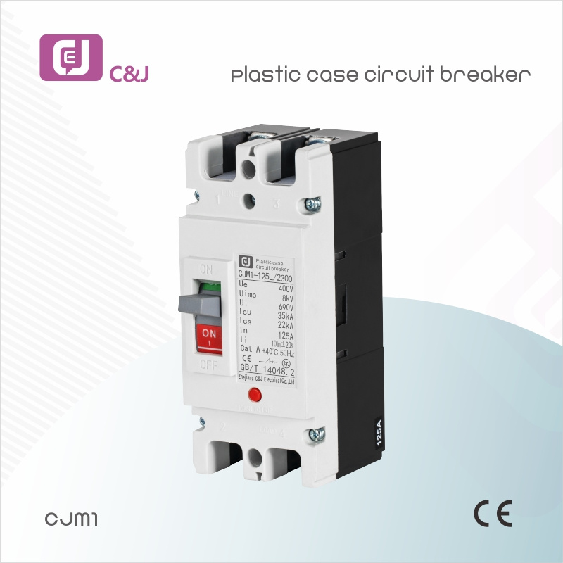
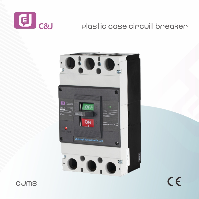
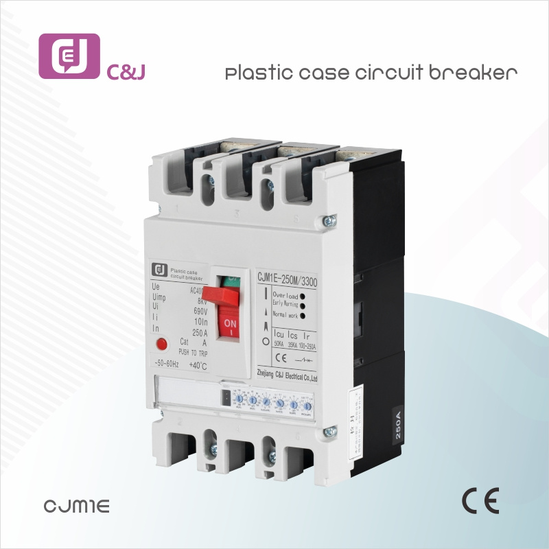
Product detail pictures:








Related Product Guide:
We strive for excellence, services the customers, hopes to be the good cooperation team and dominator business for personnel, suppliers and prospects, realizes benefit share and continual promotion for China OEM Mccb Single Phase Factory - CJMM1 Series Moulded Case Circuit Breakers(MCCB) – C&J , The product will supply to all over the world, such as: Vietnam, Croatia, Provence, Our products are widely sold to Europe, USA, Russia, UK, France, Australia, Middle East, South America, Africa, and Southeast Asia, etc. Our solutions are highly recognized by our customers from all around the world. And our company is committed to continually improving effectiveness of our management system to maximize customer satisfaction. We sincerely hope to make progress with our customers and create a win-win future together. Welcome to join us for business!
As a veteran of this industry, we can say that the company can be a leader in the industry, select them is right.


