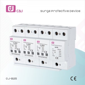
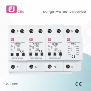
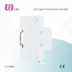
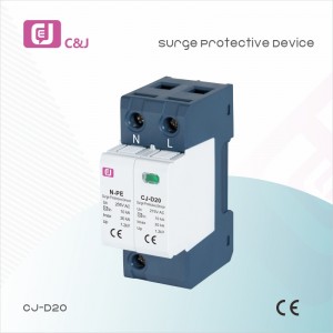
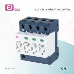
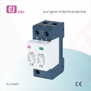
CJ-B25 4p 1.8kv Pluggable Multi-Pole Surge Protection Device SPD
Technical Data
| IEC Electrical | 150 | 275 | 320 | ||
| Nominal AC Voltage (50/60Hz) | Uc/Un | 120V | 230V | 230V | |
| Maximum Continuous Operating Voltage (AC) | (L-N) | Uc | 150V | 270V | 320V |
| (N-PE) | Uc | 255V | |||
| Nominal Discharge Current (8/20μs) | (L-N)/(N-PE) | In | 20 kA/50kA | ||
| Maximum Discharge Current (8/20μs) | (L-N)/(N-PE) | Imax | 50 kA/100 kA | ||
| Impulse Discharge Current (10/350μs) | (L-N)/(N-PE) | Iimp | 12.5kA/50kA | ||
| Specific Energy | (L-N)/(N-PE) | W/R | 39 kJ/Ω / 625 kJ/Ω | ||
| Charge | (L-N)/(N-PE) | Q | 6.25 As/12.5As | ||
| Voltage Protection Level | (L-N)/(N-PE) | Up | 1.0kV/1.5 kV | 1.5 kV/1.5 kV | 1. 6kV/1.5 kV |
| (N-PE) | Ifi | 100 ARMS | |||
| Response Time | (L-N)/(N-PE) | tA | <25ns/<100 ns | ||
| Back-Up Fuse(max) | 315A/250A gG | ||||
| Short-Circuit Current Rating (AC) | (L-N) | ISCCR | 25kA/50kA | ||
| TOV Withstand 5s | (L-N) | UT | 180V | 335V | 335V |
| TOV 120min | (L-N) | UT | 230V | 440V | 440V |
| mode | Safe Fail | Safe Fail | Safe Fail | ||
| TOV Withstand 200ms | (N-PE) | UT | 1200V | ||
| UL Electrical | |||||
| Maximum Continuous Operating Voltage(AC) | MCOV | 150V/255V | 275V/255V | 320V/255V | |
| Voltage Protection Rating | VPR | 600V/1200V | 900V/1200V | 1200V/1200V | |
| Nominal Discharge Current (8/20μs) | In | 20kA/20kA | 20kA/20kA | 20kA/20kA | |
| Short-Circuit Current Rating (AC) | SCCR | 200kA | 150kA | 150kA | |
SPD for Power Supply System Series Selection Guide
The installation of SPD at each lightning protection zone, according to the standard of low voltage electrical appearance, make classification of electrical equipment in accordance with the over voltage category, its insulation withstand impulse voltage level can determine the selection of SPD. According to the standard of low voltage electrical appearance, make classification of electrical equipment in accordance with the over voltage category as signal level, loading level, distribution and control level, power supply level. Its insulation withstand impulse voltage level are:1500V,2500V,4000V,6000V. As per to the protected equipment installation position different and the different lightning current of different lightning protection zone, to determine the installation position of SPD for power supply and the break-over capacity.
The installation distance between each level SPD should not be more than 10m, the distance between SPD and protected equipment should as short as possible, not more than 10m. If due to limitation of installation position, can’t guarantee the installation distance, then need to install decoupling component between each level SPD, make the after class SPD be protected by the prior class SPD. In the low voltage power supply system, connecting an inductor can achieve the decoupling purpose.
SPD for power supply system specification selection principle
Max. continuous operating voltage: bigger than protected equipment, the system’s max. continuous operating voltage.
TT System: Uc≥1.55Uo (Uo is low voltage system to null line voltage)
TN System: Uc≥1.15Uo
IT System: Uc≥1.15Uo(Uo is low voltage system to line voltage)
Voltage Protection Level: less than the insulation withstand impulse voltage of protected equipment
Rated discharge current: determined as per to the lightning situation of the position installed and lightning protection zone.
Write your message here and send it to us


